
In 2012, I was a PMIC Applications Engineer at a large fabless semiconductor company. I lead my colleague and I to develop a PMIC evaluation board complete with an extensive interative GUI.
The PMIC itself was very complicated and had so many functions. It had USB charging, many buck regulators, many linear regulators, LED drivers, ADC inputs, GPIO pins, a keyboard matrix scanner and a Battery Management System (fuel gauge).
Plus, the regulator voltages, configuration and logic, everything was register programmable; it had no external programming resistors or dividers.
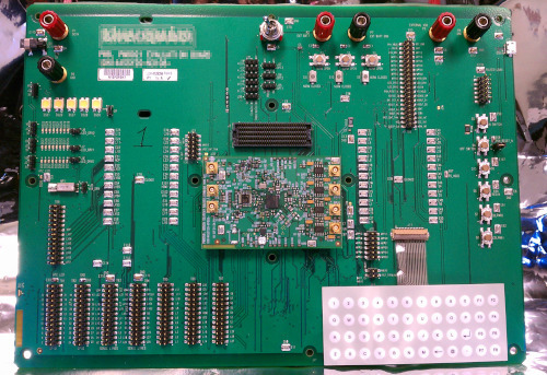
An Eval Board To Understand and Test the PMIC
As a Senior Applications Engineer, I was tasked to write the customer-facing datasheet for this massive chip. It was really tricky to figure out how all the functions worked, what bits controlled what, and how all these functions interacted just from talking to IC designers and reading design docs (many were preliminary).
So I had the idea to make a very extensive evaluation system for it, including a GUI to control and demonstrate all the features and functions on the chip. This helped me write the datasheet because I could test what I was writing immediately on the eval board.
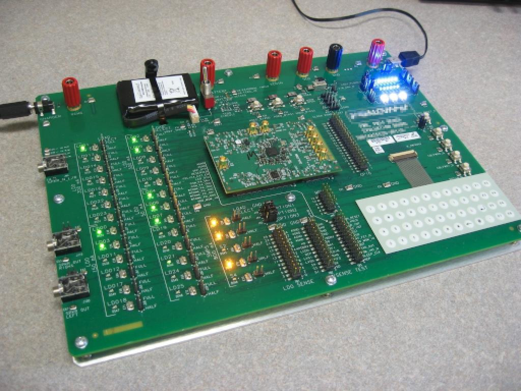
But everyone also wanted a board. Applications Engineers could emulate customers setup and help them debug issues, both internal and external firmware engineers writing code could try various register settings interactively. And all you needed was a PC and power supply.
Quite a number of these eval boards were made and sent to various departments as well as to key external customers.
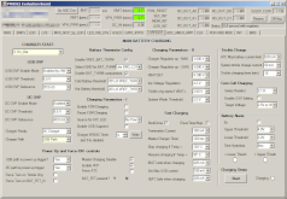
My first extensive GUI app
GUI and event driven programming were new to me at the time. An engineer from a different department gave me a Visual Basic book (circa 2012) and I learned how to use Visual Basic on Windows and write using event-driven code instead of procedural programming.
I was proud of this GUI. I took the event-driven feature to heart so not only did it allow you to control every feature interactively but it also showed real-time readings. Every status bit, the voltage of every regulator, battery and charger and the frequency of every clock output were all updated in real-time on the GUI.
Microchip Microcontroller
Between the PC and eval board, I made a custom USB interface using a PIC Microcontroller. I used MPLAB and wrote in C using the Microchip’s HAL.
Xilinx and Verilog
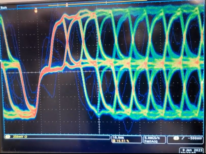
The PMIC was controlled using the company’s proprietary serial bus. The challenge was that this ran at 9.6 Mbps, way too fast to bit-bang with a low-cost microcontroller of the era.
This was probably the biggest technical hurdle. Discrete logic would have been a horrible and brittle design. I settled on using a Xilinx CPLD because it was simpler (non-volatile) and a full FPGA was not needed. I ran though Xilinx tutorials and test projects and taught myself Verilog. (I later took an official FPGA class at the university extension and got an A.)
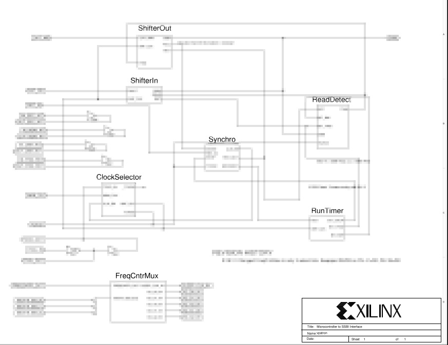
I came up with a simple design where the MCU could serially load a buffer, a string of shift registers, at its leisure. Once the correct number of bits were in, it sent the packet to the PMIC at 9.6 Mbps.
Along the way, if the packet was a read, it picked up the serial data from the PMIC and stored it into a string of shift registers.
The MCU could then serially read the data from the PMIC at its leisure.
A Useful Block
The MCU and CPLD portion of this design turned out to be a boon for another team who needed a simple way to control their RF chip with the same proprietary serial bus protocol. They incorporated it into their own RFIC eval board.